Configure Switch
It is important that you protect the trunk interface of the router with a managed switch. You should not let any client connect directly to the trunk interface – you must use a managed switch as an intermediary. One of the job’s of the switch is to enforce VLAN tagging on specific switch ports. Don’t require your clients to provide their own VLAN config: configure the VLANs on the switch itself and assign each port to specific VLANs.
Example switch
In this example, we will be working with a Sodola 9 port web managed switch (PDF manual here).
- Ports 1-8 operate at 2.5Gbps, and these will be dedicated to specific VLANs.
- Port 9 operates at 10Gpbs, and this will provide the trunk containing all VLANs.
These ports will be assigned as follows:

- Port 1 - MGMT is used only for the management of the Sodola
switch. Factory IP address:
192.168.2.1. - Port 2 - LAN (VLAN 10 untagged) -
192.168.10.1/24subnet. - Port 3 - LAN (VLAN 10 untagged) -
192.168.10.1/24subnet. - Port 4 - LAN (VLAN 10 untagged) -
192.168.10.1/24subnet. - Port 5 - WORK (VLAN 11 untagged) -
192.168.11.1/24subnet. - Port 6 - APPS (VLAN 12 untagged) -
192.168.12.1/24subnet. - Port 7 - APPS (VLAN 12 untagged) -
192.168.12.1/24subnet. - Port 8 - IOT (VLAN 13 untagged) -
192.168.13.1/24subnet. - Port 9 - TRUNK (all tagged VLANs @10Gbps.)
It is recommended to print a sticker label to apply on the top of the physical switch plate, to label each port:
Login to the management tool
Plug a workstation client into port 1 and set a static IP address of
192.168.2.2. Open your browser to http://192.168.2.1.
If you don’t have a graphical session on the client (or no browser), you can forward the port over to another workstation that does:
## From your graphical workstation,
ssh -L 8000:192.168.2.1:80 your-jump-server
Then open your browser to http://localhost:8000.
Enter the credentials when prompted:
- Username:
admin - Password:
admin.
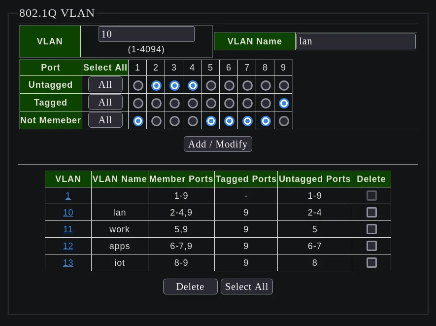
Configure switch VLANs
Find the Configuration menu.
- Find the
VLANmenu.- Find the
802.1Q VLANmenu.
- Find the
Create the following VLANs:

-
Create VLAN 10:
- VLAN:
10 - VLAN Name:
lan - Untagged Ports: 2,3,4
- Tagged Ports: 9
- Click
Add / Modify
- VLAN:
-
Create VLAN 11:
- VLAN:
11 - VLAN Name:
work - Untagged Ports: 5
- Tagged Ports: 9
- Click
Add / Modify
- VLAN:
-
Create VLAN 12:
- VLAN:
12 - VLAN Name:
apps - Untagged Ports: 6,7
- Tagged Ports: 9
- Click
Add / Modify
- VLAN:
-
Create VLAN 13:
- VLAN:
13 - VLAN Name:
iot - Untagged Ports: 8
- Tagged Ports: 9
- Click
Add / Modify
- VLAN:
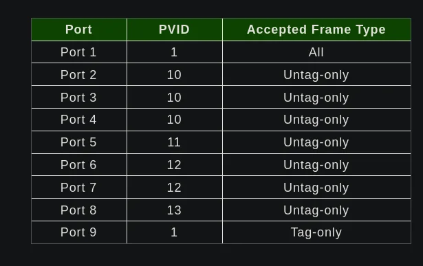
Configure the PVID of each VLAN:
- Find the
802.1Q VIDmenu:

- For each port:
- Set the PVID, which sets the native VLAN for that port.
- Set the Accepted Frame Type, which sets the expected type of data to come in that port.
- For MGMT (port 1), leave this as the default
All. - For VLANs (ports 2-8..), set this to
Untag-onlyand then native traffic will become tagged for that VLAN automatically. - For TRUNK (port 9), set this to
Tag-onlyand all traffic pre-tagged will flow unmodified.
- For MGMT (port 1), leave this as the default
By setting the ports Accepted Frame Type to Untag-Only, it makes it
very easy to configure your clients. To work with an untagged port,
you simply need to connect it to a normal (DHCP) client that has no
VLAN config. A normal (DHCP) client’s traffic becomes tagged with
the PVID assigned to that port.
The same is true if you plug another unmanaged switch into the managed switch: all traffic coming from the unmanaged switch will become tagged with the PVID of the router switch port its plugged into, no configuration is necessary on the part of the unmanaged switch or any of its clients:
---
title: One VLAN per room (with an unmanaged switch in each room)
---
graph LR
    A[Living Room = LAN]
    F[Office = WORK]
    G[Kitchen = LAN]
    C[Router Switch]
    D[Router]
    J[Laptop = LAN]
    T[TV = LAN?!]
    K[Workstation = WORK]
    L[Refrigerator = LAN?!]
    V[Laptop = LAN]

J --> A
T --> A
K --> F
L --> G
A --> C
F --> C
G --> C
C --> D
V --> G
If you have the managed router switch in a central location in a home, you can put unmanaged switches in every room that only require access to one VLAN. For rooms that require access to more than one VLAN, it requires placing another managed switch in that room, and then configuring the port for tagged traffic only, which creates a kind of sub-trunk port between the two managed switches:
---
title: Several VLANs per room (with a managed switch in each room)
---
graph LR
    A[Living Room = IOT, WORK, LAN]
    F[Office = WORK]
    G[Kitchen = IOT, LAN]
    C[Router Switch]
    D[Router]
    J[Laptop = LAN or WORK]
    K[Workstation = WORK]
    L[Refrigerator = IOT]
    T[TV = IOT]
    V[Laptop = LAN]

J --> A
K --> F
L --> G
T --> A
V --> G

A --> C
F --> C
G --> C
C --> D
Set port isolation
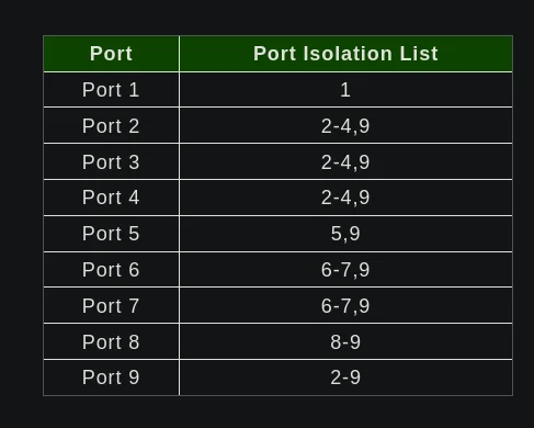
The port isolation setting can further isolate the networks between the VLAN ports. For example, ports 2,3,4 and 9 all need to talk to each other, but ports 1,5,6,7,8 should not be able to participate in those conversations. The isolation list can make this communication explicitly denied.
- Find the
Configurationmenu:- Find the
Port Isolationmenu:- Using the multi-select boxes, set the port isolation list for
each port, and then click the
Applybutton.
- Using the multi-select boxes, set the port isolation list for
each port, and then click the
- Find the
Here are the final port isolation lists of the example:

- Port 1 (MGMT):
- Isolation list:
1 - Since this is the management interface of the switch itself, it doesn’t need to talk to any other ports.
- Isolation list:
- Port 2 (LAN):
- Isolation list:
2-4,9 - LAN ports can talk to each other and to TRUNK.
- Isolation list:
- Port 3 (LAN):
- Isolation list:
2-4,9 - LAN ports can talk to each other and to TRUNK.
- Isolation list:
- Port 4 (LAN):
- Isolation list:
2-4,9 - LAN ports can talk to each other and to TRUNK.
- Isolation list:
- Port 5 (WORK):
- Isolation list:
5,9 - Since there’s only one WORK port, it only needs to talk to TRUNK.
- Isolation list:
- Port 6 (APPS):
- Isolation list:
6-7,9 - APPS can talk to each other and to TRUNK.
- Isolation list:
- Port 7 (APPS):
- Isolation list:
6-7,9 - APPS can talk to each other and to TRUNK.
- Isolation list:
- Port 8 (IOT):
- Isolation list:
8-9 - Since there’s only one IOT port, it only needs to talk to TRUNK.
- Isolation list:
- Port 9 (TRUNK):
- Isolation list:
2-9 - TRUNK can talk to any port except for MGMT (port 1)
- Isolation list:
Save the switch config
After making changes on the switch you must save the config:
- Find the
Toolsmenu:-
Find the
Savemenu:- Click the
Savebutton.
- Click the
-
Find the
Rebootmenu:- Click the
Rebootbutton to test that the config is still applied on next boot.
- Click the
-